This article was created to show users how to create a dual color print using Creatr Software 2.1.
◄What is Dual Color Printing Really?►
For now, dual color is "dual" because of the limitation of two extruder on the printer. Because this is the current standard, Creatr Software is also designed for only two extruders. However, advances are quickly being made in 3D printing, so you can expect multiple filament printers to be a big deal in the next few years.
Many people new to 3D printing assume that you can load a model into a 3D slicing software and specify which area you want to print with one filament color and what you want to print the rest. This simply isn't the case. Printing dual color prints actually requires two separate .STL models so that each extruder can be assigned to each of the two models.
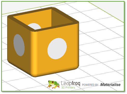
The "model" above actually consists of 2 .STL models. That means that whoever designed this box had to design the box part with empty circles on the 4 sides of the box and save the box as one .STL file. Then, they had to create a separate .STL file consisting of the four dots (or circles). The separate .STL files would then need to be assigned to each nozzle in Creatr 2.1 after importing them.
Technically, you could have more than two .STL models, but the overall print can only be two colors.
◄How to Do This in Creatr 2.1 Software►
So now that you have the general idea of what we're going to do, let's walk through the steps:
::Starting point::
- You have downloaded (or, if you're a designer, created) a set of dual color models (comprised of at least 2 .STL files).
- You've installed and opened Creatr 2.1 Software on your PC.
- You've selected your printer model from the Printer Selection Tab at the top of Creatr 2.1 software.
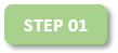
Make sure that for this, you turn of the "Autoplacement on import" option found in the Options menu:
When you select two .STL files that you want to line up, having this disabled is important. Otherwise you'll get this:

The parts will import, but will be centered and spaced evenly on the build platform.

Next, import the two models at the same time. Click the Import tab/button at the top:

... and search for the file location for both .STL models. Though we can't figure why you would have them saved in two separate locations, but for them to be aligned upon import, the two .STL models need to be saved in the same folder prior to import.
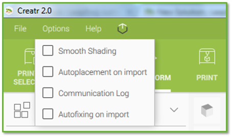
Once you find the location, click one of them, and, holding the shift key on your keyboard, click the second .STL. Both should be highlighted like in the following image:
(Yes, there is a lid to this model. For aligning the box and its dots, we'll just import the two .STL files for now.) The result of this import without the "Autoplacement on import" option selected will have the two .STL models aligned but set off of the build platform area:
The dots are the same color as the box model; you can manually adjust that on the part list to the right:

Clicking
OK with the above settings will cause the dots to turn white.
NOTE: CREATR 2.1 Software doesn't have an "Undo" command. Therefore, any mess in transforming your model will mean that you'll have to delete the models from the build platform and start again.

Now, we need to move both of these .STL models at the same time to the build platform. Upon importing, the Transform Tab automatically was selected with both models selected; You'll see some movement arms appear over the model group (see two images above). Using the X and Y movement arms only place the model group where you would like for it to print. You can also simply use the
Center button under the Move section (Transform Tab), which will center the models in the middle of the platform in terms of X and Y.
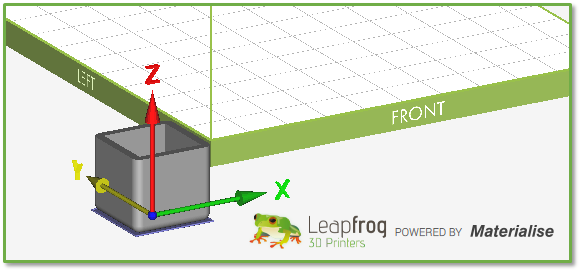
Sometimes, you'll see in the following image that after moving or clicking the Center button, the model still needs to be raised on the Z-axis. This is due to how the designer of the .STL models had the actual model placed when they saved it as a .STL file:

You cannot use the Drop Model (to platform surface) button because the dots will also drop to the build platform surface:

The dots would remain aligned on the X and Y axes but not where they should be on the Z-axis.
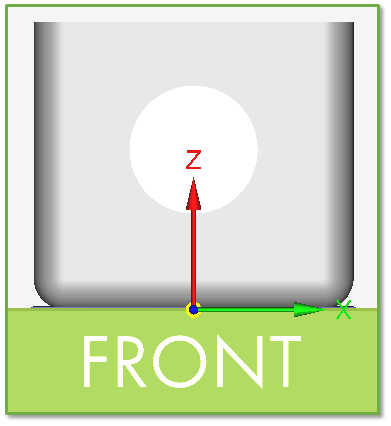
In this case the best way to get the bottom of the box on the build platform (while keeping the dots aligned) is to look at the current X, Y, and Z coordinates, make sure that both models are selected, and then type "0" in the Z-axis field and press enter:

The result, at least in this case, was a successfully zeroed box with the dots maintaining their space:

By default, all imported parts are set to print with the right nozzle. Therefore, set one of the parts to print with the Left nozzle (
L is for left,
Ris for right) by toggling the selector switch on the parts list:

In this case, I have the dots set to be printed with the left nozzle.

Now, we can select the Print Tab at the top:

This solution article is not really going to go in-depth on print profiles. However, if you have not already updated your profiles, please use the following solution article link to update your printer model's profiles: 
Select the filament type that you have loaded or plan to load in each extruder. Some people find that filament colors actually print slightly differently from one another (i.e. ABS red doesn't really print exactly the same as ABS black), so they may create slightly different print profiles for each color. Some of these differences are minor, so we won't really cover that in this solution article either.
For this example, we've decided to print with two ABS filament colors that do print similar to one another. Therefore, we can use the exact same filament profile for both nozzles:

There isn't really anything specific that you need to change in the Print Settings section of the Print Tab. By default, the "Print mode" for each nozzle is set to "Part," which is what we'll need in this case. Once, you've selected your profiles, you're ready to move on to printing.
However, when printing with dual extruders in general, it is recommended to use an Auxiliary structure; this prints a small layer of filament off to the side (forming a rectangular tower... or auxiliary structure). This is an option in your Build Strategy profile:

This helps to prime the nozzles and possibly wipes any oozing filament from the nozzle not in use.

Depending on your printer model, the next step involves deciding if you're going to print with your printer connected to the PC or via USB stick; Creatr Single, Dual, and XL models only can print connected to the PC; Xeed cannot connect to the PC (because there is no need to - it has it's own internal PC).

You can always preview the print by clicking the
Print Preview button (and then the
Exit Previewbutton when you're done).
If you're saving the .GCODE to a file to print it in a Stand-Alone mode for a printer (the only option for the Xeed), click the Generate GCODE button where you will be prompted for a location, to name the file, and then to click the Save button.
If you're going to print connected to a PC, have the printer turned on, the printer-to-PC USB cable connected, the Connect to PC menu option selected on your HS or HS XL display (if you have that model of printer), select the correct COM port in Creatr 2.1 software, and click the Connect button (You'll know when the software is connected when the Connect button turns to a Disconnect button and you're able to manually move the print head.

Finally, set up your printer with the correct filament types in the correct extruders (the color according to how you want your model to print), and make sure that the bed has been leveled and that you've applied the proper adhesive material to the bed. It is recommended in most cases to preheat and extrude a little bit of filament from each extruder (wiping what is extruded with a thick cloth); then home the printer before starting the print.
That's it! We hope that this helps you print some really creative dual color prints.
We thank you for checking out our Leapfrog 3D Printer technical support solutions online! If you were unable to fine a solution in our database, please feel free to open a new support ticket by clicking the following link: I want to open a new support ticket.